What is Alignment?
Advertisement
- It is the process of positioning two (or more) machines that are coupled, so that Center lines of rotating shafts form a single line when the machines are working at normal operating temperature.
Coupling alignment
- A coupling alignment is a device used to connect two or more machine shafts together for the purpose of transmitting power. Coupling design factors in many variables, such as horsepower,load, specific gravity, head pressure, torque, shaft sizes, safety factors etc.
Advertisement
Flexible Coupling
- Flexible coupling can handle some misalignment but it will generate heat and it will impose forces to the shafts.
- This will create vibrations,and couplings, seals and bearings will fail prematurely.
- A flexible coupling is however, necessary to handle the movement from cold to hot condition.
What is misalignment?
- Shaft misalignment is considered the second most prevalent source of vibration after imbalance, it occurs due to poor alignment between corresponding components, such as coupling halves, clutches, shafts, pulleys, etc.
Advertisement
Types Of shaft Misalignment
1. Off set
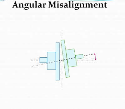
2. Angular
3. Skew - Combination of offset & angular
1). Offset misalignment:
2). Angular misalignment
Causes Of Misalignment
- Thermal expansion - Most machines align cold.
- Forces transmitted to the machine by pipe or support structure.
- Soft foot.
- Poor workmanship.
Effects Of Misalignment
- More than 50% problems are due to misalignment.
- Causes vibration on the machine
- Vibration destroys critical parts of machines like bearings, gears, seals, coupling etc.
- Breaks lubricant film inside the bearing and increase friction.
- Increases load on the bearing.
- Increase 2 - 17% power consumption.
- Generates heat inside the coupling.
Recognition of Misalignment
1. Excessive Radial & Axial vibration
2. Premature / repetitive failure of bearing, seal, coupling.
3. Loose coupling elements.
4. Leakage from the seal.
5. Loose base bolts.
6. Coupling become hot while running.
7. High casing temperature.
Types of alignment system
Advertisement
1. Rough Alignment
• Using straight edge, Ruler, Feeler Gauge
• Twin wire method
2. Precision Alignment
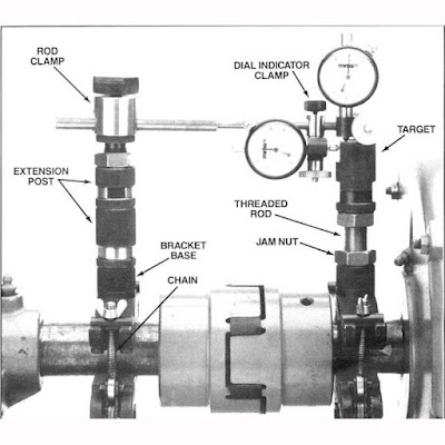
• Using dial gauges
• Using Lasers
Rules For proper Alignment
- Clean the machine base.
- Remove rust burrs etc.
- Use steel or brass shims. Check indicator sag.
- Perform pre-alignment checks on Machine.
- Check dial gauges before taking readings.
- Use correct bolt tightening procedure.
- Don’t lift the machine more than necessary.
- Try to put the stem of dial gauge perpendicular to the surface of coupling.
- Use jack bolts.
SAFETY PRECAUTIONS
- Before commencing work. Observe proper lock-out,Tagging and Isolation procedures. This may include purging of pumps and eliminating all stored energy.
- Ensure all tools are in good condition and correct for the job. Use mandatory PPEs.
Advertisement
Pre-alignment Checks
The Secret to Fast Alignment
- Reduces errors
- Reduces re-work
- Machines maintain alignment position
- Simplifies the alignment procedure
Pre-alignment Procedures
- Checking run out
- Checking pipe strain
- Correcting gross soft foot
- Setting the coupling gap
- Rough alignment
- Torquing bolts
- Precision soft foot
Laser shaft alignment
Advertisement
- Light Amplified By Stimulated Emission Of Radiation Laser was originally emitted by charge sent through a gas mixture of Helium & Neon. Now it is generated by a low power semi conductor diode with collimating lenses. Modulated to avoid interference from other light source It is collinear. Single wave length of 670 nm. Class II Laser is used for Laser Alignment System.
Laser alignment tool
- A laser shaft alignment tool performs measurements by means of two sensors mounted on two connected shafts. Both sensors fire a laser beam and receive the other sensor's beam simultaneously; a comparison of the beams reveals whether the shafts are aligned and within a specified tolerance.
Advantages:
Advertisement
1. Easy to use.
2. Use Reverse Indicator Method.
3. Machine does the calculations.
4. 0 - 20m max. working distance.
5. Selectable high resolution 0.1, 0.01, 0.001mm.
6. No indicator sag.
7. Soft foot measurement program.
8. Horizontal shaft alignment with mim 600 rotation.
9. Vertical shaft alignment program.
10.Thermal or offset compensation.
11. Machine train alignment program.
12. Cardon shaft alignment.
13. Straightness, Flatness, Perpendicularly,
Parallelism measurement.
14. Spindle alignment.
15. Static feet correction.
16. Continuos monitoring.
If you need the pdf document, it is available for download in our blog comment section.
Advertisement


Download Link - https://cutt.ly/zZh3thn
ReplyDeletePost a Comment